|
|
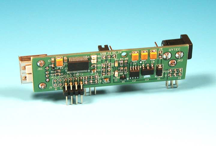
The new FT232RL based RoadRunner stick provides
a flawless USB
interface and a versatile power supply for making experimental circuits on solderless breadboards. It is not only designed to be used with our
ThunderBird12 and Dragonfly12 stamp modules, but also with any microcontroller
ICs or modules that can be
plugged onto a solderless breadboard.
It works with all operating systems
including Windows 98, Windows XP, Vista 32/ 64 bit
Windows 7 and linux flawlessly.
If the USB to TTL interface is not used,
the RoadRunner stick can function as a compact 5V power supply for
temporary prototypes and experimenting with circuit design on a
solderless breadboard.
RoadRunner features:
- Includes the FT232RL to provide USB to TTL
conversion.
- Works flawlessly with all operating systems
- Power source selectable from a USB port or
an external AC-DC adapter by a jumper
- Provides 500mA DC at 5V or 300mA at 3.3V.
- Power LED indicator for 5V or 3.3V
- Installed with a dual function 500mA fuse
jumper
- Pinouts of the SCI communication match the
ThunderBird12 module
- Red and Green LED indicators for serial data
communication
- Works with the ThunderBird12 module without any
jumper wire.
- Provides USB to TTL interface and power to any
microcontrollers
- Zig Zag pin layout for fitting a breadboard
perfectly
- Includes a 6 foot USB type B
cable
Install and verify USB driver:
-
Before connecting the
RoadRunner module to your PC's USB port for the first time, make
sure that the module is unplugged from a breadboard.
-
Go to the FT232RL driver
installation and verification page for operating procedures:
http://www.evbplus.com/TinyUSB_9s12/ft232rl.html.
-
Once you have verified that the USB
driver is properly installed, you may
now plug the RoadRunner module onto a breadboard and connect it to a
microcontroller module such as our ThunderBird12 or Dragonfly12 module.
Invoke the AsmIDE if the microcontroller module is pre-loaded with Freescale D-Bug12 monitor, or
invoke Code Warrior if the module is pre-loaded with Freescale serial monitor.
-
For
using Code Warrior with Freescale serial monitor you need to
Download and configure Code Warrior
http://www.evbplus.com/Code_Warrior_hcs12.html
-
If the
AsmIDE does not communicate with your microconroller module then you need to check if
the COM port number that is assigned by the AsmIDE matches the
USB-to-Serial COM port number that is
assigned by Windows' Device Manager. The Device Manager assigns the
USB-to-Serial COM port number randomly and it does not know which COM port
number that AsmIDE is going to use.
In order to find the USB-to-Serial COM port number
that is assigned by Device Manager, you can click through
"Control Panel -> Systems -> Hardware -> Device Manager -> Ports".
The
USB-to-Serial COM port number will appear (In Windows Vista, you left click
on Start, right click on Computer, left click on propriety, then Device
Manager and then Continue).
For setting the COM port of the AsmIDE to match that USB-to-Serial COM port
number, you can click through "View-> Option->Terminal Window Options" menu,
then select the correct COM port from COM1 to COM8.
Note:
( This note applies to Code Warrior IDE as
well )
In order to establish a reliable USB
communication, always connect the RoadRunner to your PC's USB port first
before invoking the AsmIDE, otherwise the AsmIDE will not be able to
find a COM port. When ending a debugging session, always close the
AsmIDE first before unplugging the USB cable from the RoadRunner, otherwise
the AsmIDE may hang up and you need to re-establish USB communication again.
As long as you keep the
RoadRunner
connected to your PC's USB port, disconnecting the RoadRunner from
your microcontroller module or unplugging the RoadRunner from your
breadboard will not lose USB communication.
In case the AsmIDE hangs up,
you need to close the AsmIDE first, then unplug the USB cable from
your RoadRunner, wait a few seconds before re-plugging the USB cable,
then wait a few more seconds and allow the USB connection to be
re-established. After cycling the USB connection you can invoke the AsmIDE again and it may
restore the USB communication. If this does not work, you need to restart
your PC, but in order to avoid this, always close the AsmIDE before
unplugging the USB cable.
If
restarting the PC does not solve the problem, you may need to re-install
the USB driver.
Operating
instructions:
The circuitry of the RoadRunner module is
very simple and you probably would know how to use it by reading the
schematics.
It provides a USB to TTL conversion for a serial communication and a 5V
or 3.3V regulated power supply. The serial communication supports
xon-xoff protocol and the handshaking signals /RTS and /CTS are
available on the module, but are not being used.
Although its main application is to team up with our ThunderBird12 or
Dragonfly12 module to form a quick prototype platform, but it will also
work with other micro controller module as well.
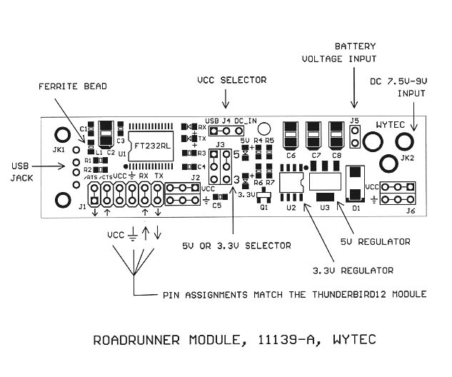
1. The J4 is used to select the VCC source for the module. It's a dual
function polyfuse jumper.
When the jumper is placed toward to the USB jack the USB port provides
the VCC for the module.
When the jumper is placed toward to the DC jack you need an 7.5V-9V AC
adapter to provide the VCC for the module.
2. The J3 is used to select voltage level for the VCC. Both jumpers must
be moved togerther vertically.
When they are placed in the "UP" position the VCC is 5V and the 5V LED
indicator will be lit.
When they are placed in the "LOW' position the VCC is 3.3V and the 3V
LED indicator will be lit.
The 5V voltage from a USB port is very convenient for testing program
code, but if you are going to test motor or other power devices, they
might cause a reset on a ThunderBird module if they draw too much
current and force the VCC drop below 4.5V. If that's the case you should
use an external AC adapter instead of getting power from USB or a
separate power supply unit for the power devices.
The default setting of the J3 is for 5V and the J4 is for USB port.
When it's plugged onto a solderless breadboard it can provide VCC and
ground buses for the breadboard.
It also provides VCC, ground and SCI communication signals for the
ThunderBird12 module or the Dragonfly12-Plus DIP module.
If it's used with a ThunderBird12 module:
1. Plug the RoadRunner onto a soldless breadboard.
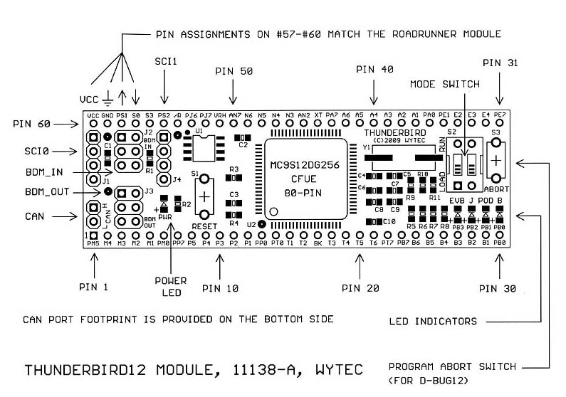
2. Plug the ThunderBird12 module and align the pin 57 - pin 60 of the
ThunderBird12 module, pin to pin, to the J1 of the RoadRunner.
When the ThunderBird12 module is pre-installed with bootloader and
D-Bug12 monitor, the states of the 2-position DIP switch (S2) are tested
by the bootloader for selecting one of 4 operating modes during power up
or reset, and the four LED indicators will light up from left
to right to indicate that the bootloader is functioning. Then one of
them will be lit to indicate the selected operating mode and other three
will be turned off. When you learn HCS12 / 9S12 programming with D-Bug12
monitor, you might need to change operating modes quite often, so a mode
indicator is helpful.
The 4 operating modes tested by the bootloader are EVB, Jump to EE, BDM
POD and Bootloader.
When the ThunderBird12 module is pre-installed with serial monitor, the
state of the left switch of the 2-position DIP switch (S2) is tested by
the serial monitor for selecting RUN or LOAD mode during power up or
reset, and the four LED indicators will light up from right
to left to indicate that the serial monitor is functioning. If the left
switch is placed in "LOAD" mode the monitor will wait for a command from
PC. If the left switch is placed in "RUN" mode the LEDs will
light up again
from left to right to indicate that the program execution is diverted to
the user code.
If the bootloader or the serial monitor is not installed or erased by a
BDM, the 4 LED indicators will not light up sequentially during power up or reset.
If it's used with a Dragonfly12-Plus module
based on the MC9S12C32 or
MC9s12C128, you need make 4 connections for the
Dragonfly12-Plus module: see the wiring in the picture at:
http://www.evbplus.com/Dragonfly12P_9s12/DIP40_9s12.html
1. Plug the RoadRunner onto a soldless breadboard.
2. Connect the pin 1 of the Dragonfly12-Plus module to GND.
Connect the pin 2 of the Dragonfly12-Plus module to VCC.
Connect the pin 34 (PS0) of the Dragonfly12-Plus module to
the TX output of the RoadRunner module.
Connect the pin 35 (PS1) of the Dragonfly12-Plus module to
the RX input of the RoadRunner module.
The Dragonfly12-Plus module is pre-installed with serial monitor only,
because it does not have enough flash memory to hold the D-Bug12
monitor. The state of the slide switch (S2) is tested by the serial
monitor for selecting RUN or LOAD mode during power up or reset, and the
LED indicator will blink twice to indicate that the serial monitor is
functioning. If the slide switch is placed in "LOAD" mode the monitor
will wait for a command from PC. If the slide switch is placed in "RUN"
mode the LEDs will flash 2 more times to indicate that the program
execution is diverted to the user code.
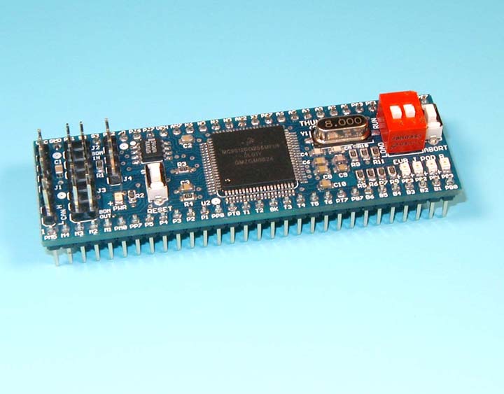
9S12: ThunderBird12 DIP
module
Get more info. of the ThunderBird12
at:
http://www.evbplus.com/ThunderBird12_9s12/ThunderBird12_9s12.html
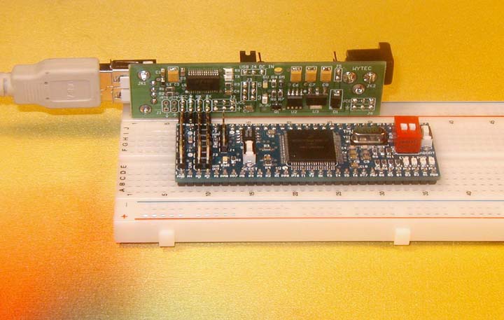
When the ThunderBird12
module is combined with the
RoadRunner USB+POWER stick it becomes a versatile minimal
prototype system. It will make your prototyping much neat and reliable.
The clumsy DB9 cable, a USB to RS232 adapter and a bulky AC to DC adapter are replaced by a light USB cable with a 5V power source
directly from a laptop, it's a laptop friendly system and students can even do homework while enjoying the
outdoor life.
 |
 |
|
ThunderBird12 and RoadRunner form
a prototype system |
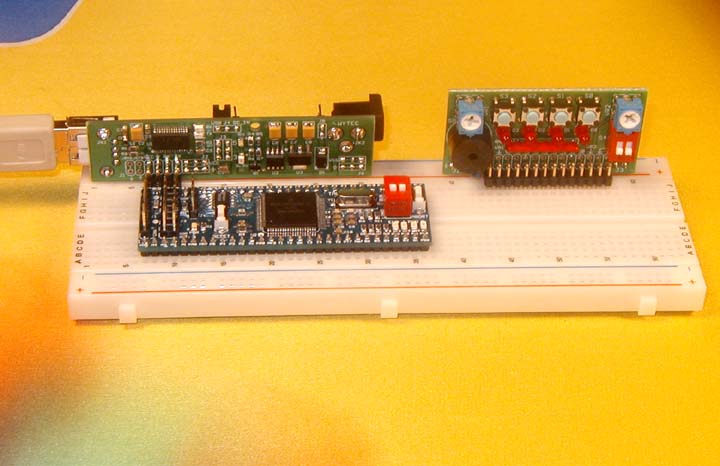
ThunderBird12, RoadRunner
and an I/O module |
|