|
|
Product Code
|
Price (USD)
|
Description
|
DF12P-BBU
DF12P-BBU-C32
DF12P-BBU-C128 |
$59
$78$83
|
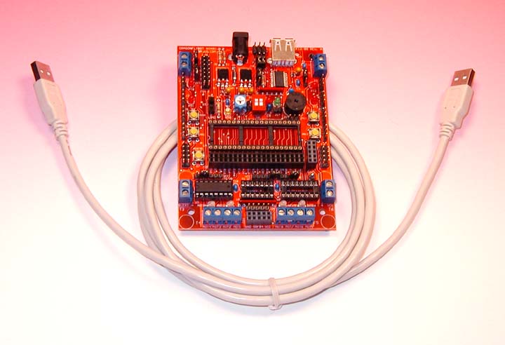
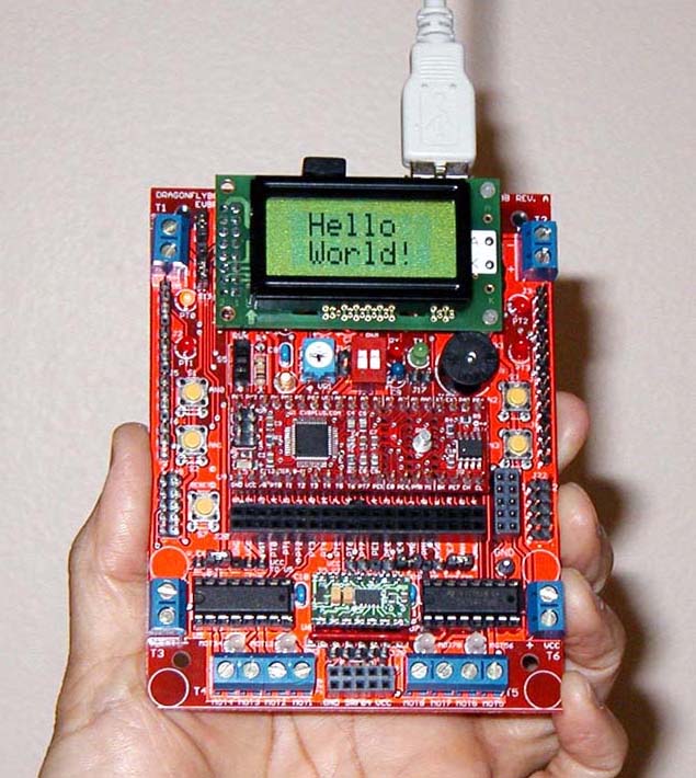
DragonflyBot
Board with USB port for Dragonfly12 plus module
DragonflyBot Board
with USB port and Dragonfly12 plus C32 module
DragonflyBot Board
with USB port and Dragonfly12 plus C128 module |
Each price includes a USB cable as shown on the
above picture.
Application:
- Advanced Robot controller
- Possible replacement of the legendary Handyboard designed by MIT's Fred Martin
- Possible replacement of the legendary Botboard+, Botboardplus designed by Marvin
Green, Kevin Ross and Karl Lunt
Features:
- Uses the low cost Dragonfly12 DIP module as the controller
-
Installed with Freescale's serial monitor for
working with CodeWarrior
-
On-board USB interface for programming and debugging
code, no BDM needed
-
USB TX and RX indicator LEDs
-
Fits on the Parallax's BoeBot chassis
-
Auto-start user application program from on-chip
flash memory via a slide switch
-
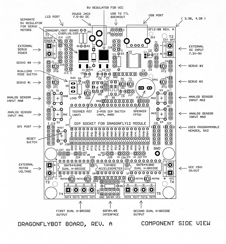
Four servo outputs with selectable supply voltage
for servos
-
Dual H-Bridges control two DC motors or one stepper motor (can be
expanded to quad H-Bridges to control 4 DC motors or 2 stepper motors)
-
Accepts Davantech SRF04 or SRF05 Ultrasonic ranger module
-
Separate 5V voltage regulators for Servos motors and microcontroller
circuits
-
Accepts 4 GP12D120 distance-measuring sensors or other analog or
digital inputs.
-
Socket provided for TinyBee 3-Axis Accelerometer in a 14-pin DIP.
- Four LEDs connected to port T
- Four Bi-Direction LEDs for DC motor directions.
- A 2-position DIP switch
- Four
analog or digital sensor inputs
- Four push button switches
- On-board speaker
- On-board potentiometer trimmer pot for ADC input
- 20x2 female header provides all I/O ports for quick prototyping user
circuits on solderless breadboard.
-
LED power indicator
-
5x2
user programmable male header for interfacing a line follow module
-
5x2
male header for a SPI port
- Package also includes useful software:
- Fully debugged sample programs including source code
- Test program that simultaneously plays a song and flashes PT0-PT3 LEDs.
- Test program for TinyBee accelerometer
- Can be used as a USB breakout board
- Small PCB size of 3.3" X 4.3"
Options:
- Plug-in 8x2 LCD module with backlight
-
Second dual H-Bridges control two more DC
motors or one more stepper motor
-
TinyBee Accelerometer module in 14-pin DIP
-
9V 300mA AC adapter
-
Breadboard ( it comes with 4 rubber feet attached that
can be stacked onto the board)
The BBU board comes with a
built-in USB interface based on the FT232RL. The driver for the FT232RL must be
installed properly before using the BBU board.
Install and verify USB driver:
-
Before connecting the
BBU board to your PC's USB port for the first time, make
sure that the AC adapter is unplugged. You do not need to turn on the board to
install USB driver.
-
Go to the FT232RL driver
installation and verification page for operating procedures:
http://www.evbplus.com/TinyUSB_9s12/ft232rl.html.
-
Once you have verified that the USB
driver is properly installed, you may
turn on the BBU board and invoke the Code Warrior IDE.
-
If you
have not installed Code Warrior you need to
Download and configure Code Warrior
http://www.evbplus.com/Code_Warrior_hcs12.html
Note:
In order to establish a reliable USB
communication, always connect the BBU to your PC's USB port first
before invoking the Code Warrior, otherwise the Code Warrior will not be able to
find a COM port. When ending a debugging session, always close the
Code Warrior first before unplugging the USB cable from the BBU, otherwise
the Code Warrior may hang up and you need to re-establish USB communication again.
In case the Code Warrior hangs up,
you need to close the Code warrior first, then unplug the USB cable from your
BBU, wait a few seconds before re-plugging the USB cable,
then wait a few more seconds and allow the USB connection to be
re-established. After cycling the USB connection you can invoke the
Code Warrior again and it may
restore the USB communication. If this does not work, you need to restart
your PC, but in order to avoid this, always close the Code Warrior before
unplugging the USB cable.
If
restarting the PC does not solve the problem, you may need to re-install
the USB driver.
The BBU board draws insignificant
current and can be powered by 5V supply of a USB port. The voltages for the servos and motors can be
brought in via terminal blocks.
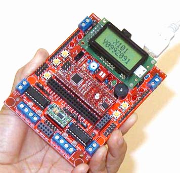
The BBU installed with Dragonfly12 DIP module, LCD display module, TinyBee accelerometer module and the
2nd dual H-Bridge driver SN754410
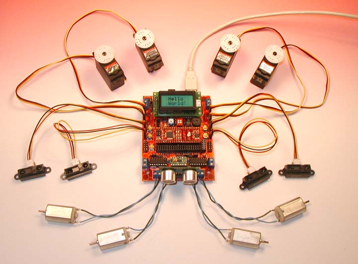
The BBU can control 4 servos or 4 DC motors or 2 stepper motors and monitor 4
digital or analog inputs, such as GP2D120 IR sensors. It also can use a SRF04/SRF05 Sonic Range
Finder to detect objects.
Some robots such as the following two can be controlled by the DragonflyBot
Board without much external parts:
http://wwweng.uwyo.edu/electrical/faculty/barrett/68hc12//Robot_Owners_Manual_web.pdf
Controlled by a MiniDragon+ board
http://www.coe.montana.edu/ee/seniordesign/archive/FL07/micromouse_bcp/hardware.html
Controlled by a Dragonfly12 DIP module
The
board is pre-installed with serial monitor and a test program. It comes
with a USB cable and it is set for using VCC from USB port. You don't need to
connect an AC adapter in order to test the board.
When
the board is plugged into a USB port via the USB cable, it will run the test
program if the slide switch S5 is in "up" position
("Run" position). Press
the pushbutton S1 the LED flashing speed will increase, press S2, the speed will
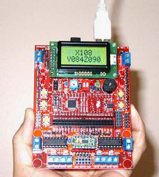
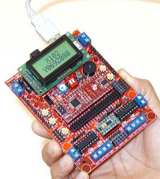
decrease. Press S3 it will display accelerometer's X-Y-Z values
on LCD display. Each count represents 5V/256=19.53mv.
The above pictures show different values in Y- axis when the board is tilted.
On the left: voltage on Y axis is
099 x 19.53mv =1.93V
On the middle: voltage on Y axis is 084 x 19.53mv =1.64V
On the right: voltage on Y axis is 069 x 19.53mv
=1.35V
The VCC of the TinyBee-2 module can be 3.3V or 5V. In analog mode used
in BBU, the VCC of the TinyBee-2 module is 3.3V. In a 3.3V system, 1.65V (half of the 3.3V) represents zero
acceleration or in horizontal position. When this accelerometer is
tilted, the voltage range is between 1.23V to 2.11V. With 19.53mv per count
the count range is 63 to 108.
Not many robots need an accelerometer. In a few applications it can be used
for detecting uphill, downhill, or even a flip over. It's also useful in a
wall-climbing robot.
Because the size of BBU is small, the TinyBee module may have more different
applications in standalone embedded products where the BBU is used as the
controller board.
|